
AI Just Solved 3D. Here's How We Designed an Observatory House in Alentejo, Portugal
Guest post: How Darkmatter uses AI to connect design, 3D modelling, engineering and science, with Casa do Poente as a practical case study.
By Darkmatter
Sep 7, 2026 · 24 min read
At Darkmatter we use AI to write the code that builds our 3D models. This is how we designed Casa do Poente: a house, a windmill lounge and a telescope observatory in Alentejo, Portugal. The engineering calculations changed the design more than once. Nothing is built yet, and the method is free to copy. A guest article for Poolside.
A place for guests and for telescopes
Casa do Poente began with one question: can a family house, a guest business and a working observatory share the same piece of Alentejo? The brief asked for bedrooms, a library and a workshop alongside the telescopes. A guest who owns no equipment should be able to join a guided session, and the same site should carry instruments doing long-exposure photography and scientific work.
Guests need light to find their way, and rooms they can close the door on. Telescopes need darkness, an open horizon, supports that do not move, and shelter from weather and animals. A path that suits a visitor at night has to stay clear of equipment that swings.
Here is the scope, stated once so nothing later needs hedging. Casa do Poente is a design study. Nothing is built, the land is not bought, the site is not surveyed, no design has been through planning approval and no instrument has been ordered. Every figure below comes from a model, a published specification or an advertised listing, not from a measurement on the ground, and every view is a render of that model, not a photograph of anything that exists. The reasoning is what we are publishing, including the decisions we reversed.
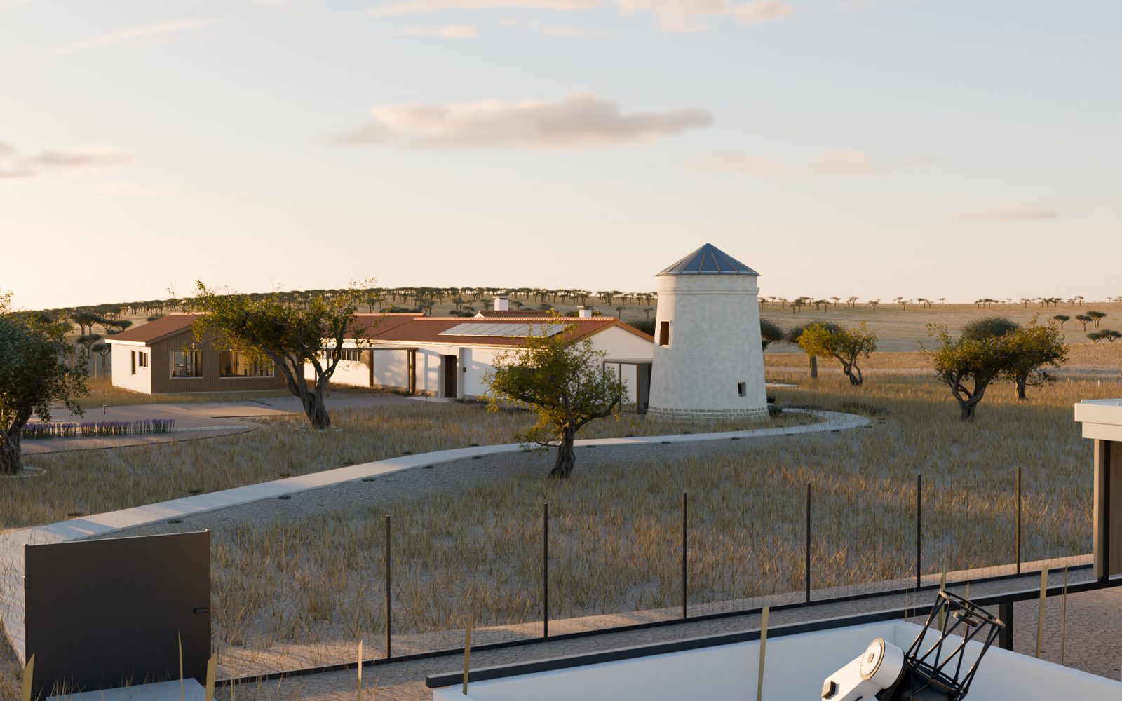
The windmill was the first place we put the observatory. A later review moved it to ground level and left the windmill as a lounge.
The four views below come from an earlier round of the model: the estate from the air, then cutaways of the main house, the private wing and the pavilion. Roofs are hidden in the cutaways and still present in the model.
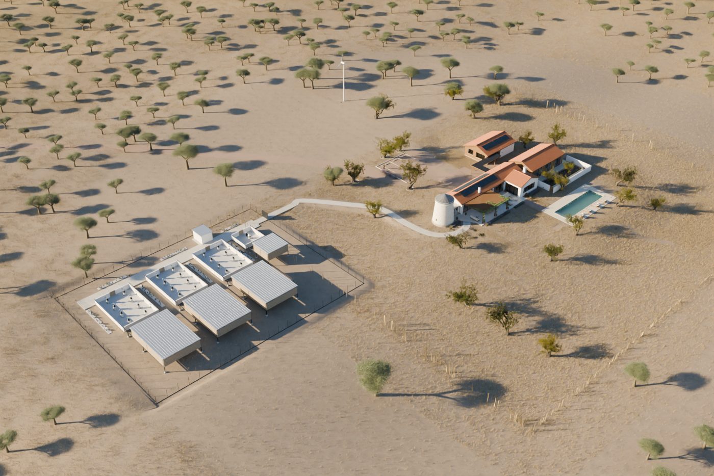
The estate in our model: the windmill under a closed roof, the telescope on its own ground. The three house sections below come from an earlier round.
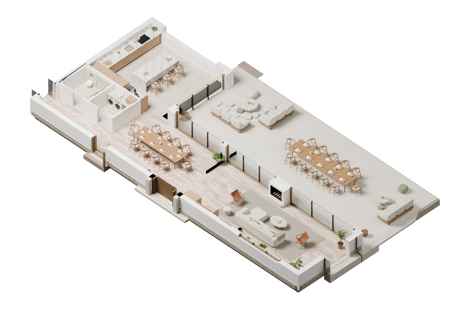
The main house, cut open. The roof is hidden for this view but still in the model.
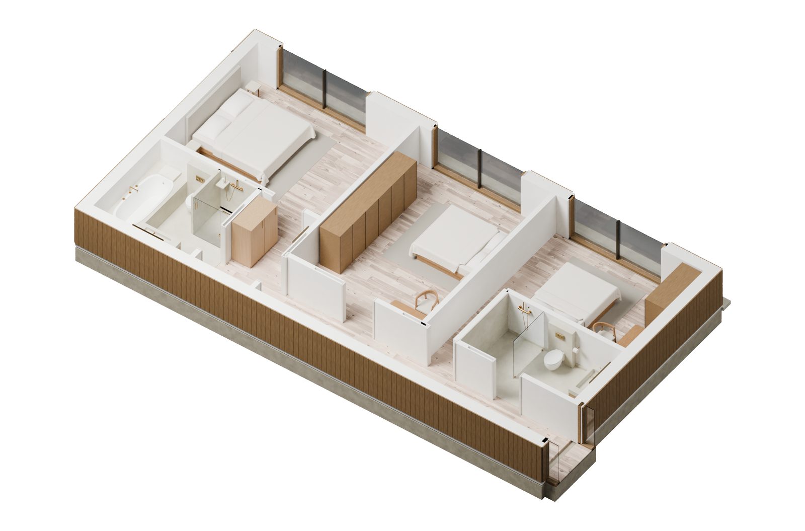
The private wing: bedrooms, the enlarged suite bathroom and the route between them.
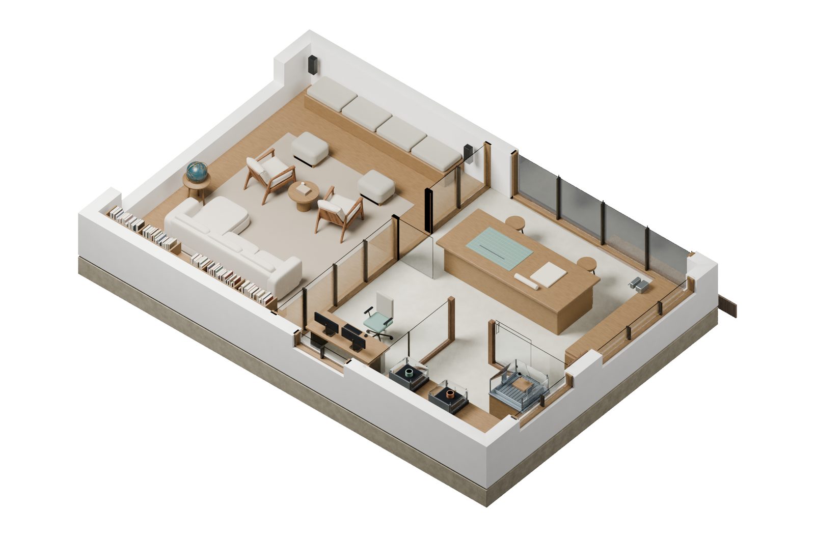
The pavilion: library and reading space, a shared making area and an equipment room.
Looking for a site
We needed a dark sky, an existing structure worth keeping, usable road access, a town close enough for guests and services, and enough land to keep house, pool, observatory and wind turbine apart. Évora sits inside the territory listed by Dark Sky Alqueva. That makes the region a sensible place to look, and says nothing about the sky at any one plot.
We checked advertised mill properties against those requirements. One near Portel advertises 4,999 m² with a 71 m² mill ruin, but was marked Reserved when we looked. Another, at São Martinho das Amoreiras, advertises a 29.54 m² mill on 788.75 m² of land. That is too small to keep a pool and a turbine away from an observatory.
Our leading candidate is a 7,500 m² smallholding with an old windmill near Nossa Senhora de Machede, about 20 minutes by car from Évora, the agent says. The listing advertises flat ground, roughly 120 metres from a paved municipal road, services still to be installed, and room for a 275 m² gross house with a pool. Those are advertised figures, recorded on 5 September 2026.
The map pin on the listing seems to point at the wrong place. Against OrtoSat2023, the 2023 satellite mosaic published by Portugal's national mapping agency, the pin sits inside the village while the building that matches the listing photographs sits about 1.1 km east of it. That is a small version of what this study does: let one source correct another before the model rests on it.
Two frames from that imagery, one regional and one covering 800 metres around the apparent mill, gave us the field and grove patterns, five farm-track centrelines and the land colours. Terrain and tree heights, the mill's dimensions and the siting of house, pool, parking and turbine are our interpretation on top.
The advertised plot looks long and narrow, so the area figure alone does not tell us our layout fits inside it. That answer arrives with a boundary survey and the council's answers on access, water and drainage.
Measuring sky darkness
Start with a regional light-pollution map. Satellite readings and modelled sky brightness screen locations well. Conditions where the telescope will stand have to be measured from that spot, which is why the map provider keeps those layers separate. Light Pollution Map methodology
The survey we propose points a meter straight up and in other directions, at a few heights, across the seasons. Every reading logs the instrument, the time, the Moon's position, the cloud and any local lighting. Tests with the house lights on and off would show what the building adds. Air steadiness, blocked horizon and the count of usable nights are assessed separately. How to measure sky brightness
Sky brightness translates directly into exposure time. In a simplified case where sky glow is the limit, going from 21.8 to 20.5 magnitudes per square arcsecond needs about 3.3 times as much exposure for the same image quality. Those two values are comparison scenarios, not measurements.
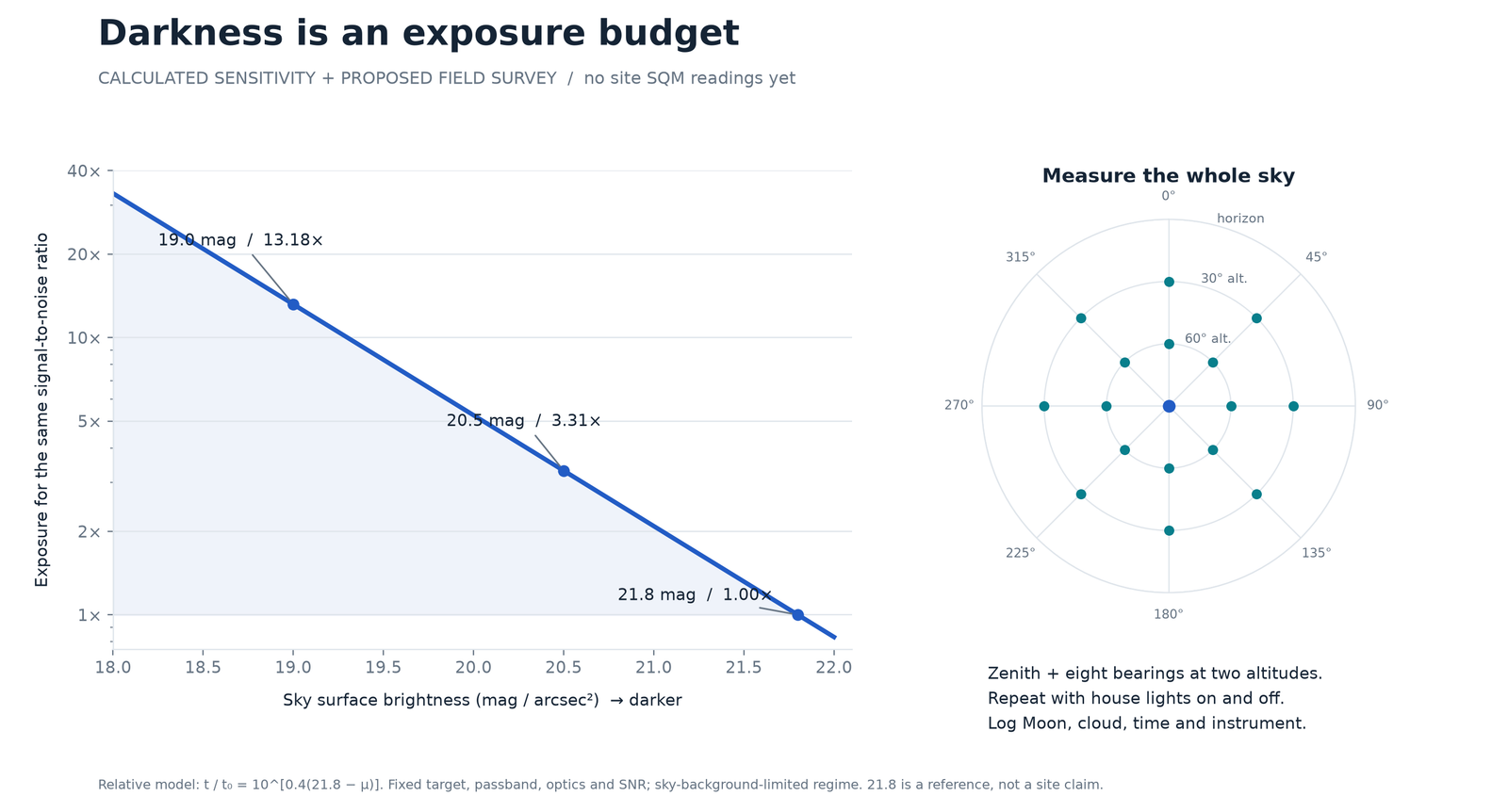
Higher magnitude numbers mean a darker sky. The chart fixes the target, the optics, the filter and the image quality. Real exposure planning also depends on camera noise, saturation and the object photographed.
The lighting plan needs shielded fixtures, low output and control of the light escaping through windows. Pool lights go off during sensitive observing. Dim red path lights keep people moving safely, and indoor lamps, blinds and screens belong in the observing mode. DarkSky and IES lighting principles
Architecture and 3D modelling with Astra
It started on paper. One page of a sketchbook: the house in plan, the same building in elevation below, and the old mill with a dome on it and the word observatory beside an arrow. Ballpoint, no scale, no dimensions. We handed that page to Astra and got back geometry we could measure and walk through. Here is that page, and beside it the same idea in the model, rendered in Blender.
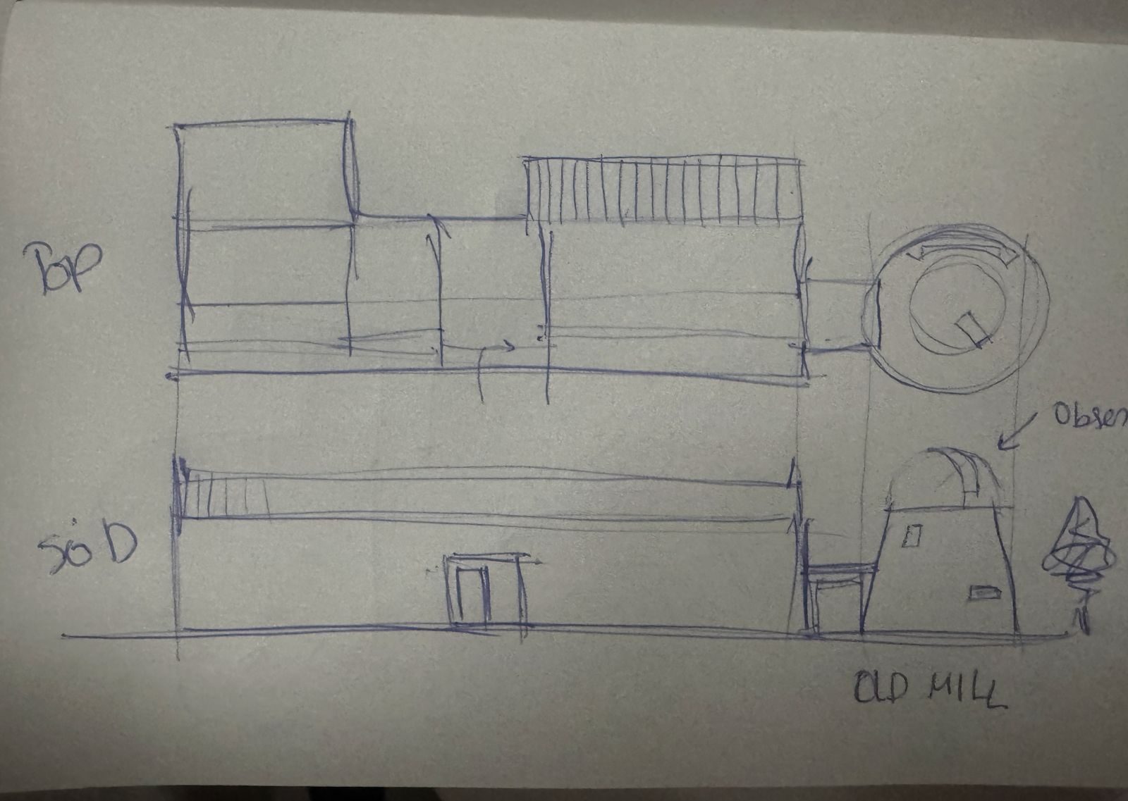
The sketchbook page that started it. Ballpoint, no scale, no dimensions.
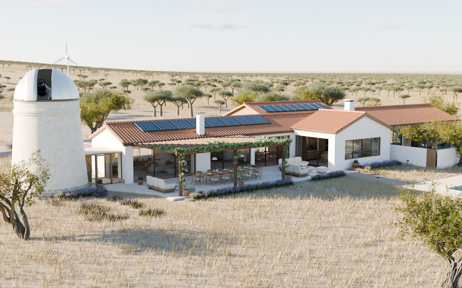
The same idea in the model, rendered in Blender. The mill still carries the dome the sketch gave it.
A drawing like this used to be the start of weeks of drafting before anyone could say whether the idea held up. Now the sketch is the brief, and the model comes back quickly enough that the first useful thing you do is argue with it. The dome on the mill makes the point: it survived from this page into the model, and then the structural work took it out again.
The model is built by code. GPT-6 Astra, in Codex, writes and revises the Python scripts that assemble the Blender scene. A note scribbled on a render is not a wish list: Astra reads it, changes the geometry and renders the view again. We set the brief and judge the result. Introducing GPT-6 Astra
We ran this loop from the Darkmatter lab at Poolside Santos in Lisbon, and we are sharing the work as a free case study so others can copy the method.
Changes rarely stay where you make them. Moving a fireplace away from the telescope pulled the wall, the glazing and the roof outlet with it. Adding a bathtub meant enlarging the suite bathroom.
The workflow others can adapt has five stages:
- Set dimensions and units. Build in metres, from references and published dimensions.
- Explore the design visually. Image generation settles the mood of a room, its materials and the furniture direction. We keep those images as references, with their origin visible.
- Build editable components. Chairs, tables and other pieces become named components, each with a fixed origin, a consistent orientation and its own geometry and materials.
- Review the parts and the whole. Front and side renders of a single piece expose bad joints and proportions. Furnished plans, cutaways and eye-level views expose blocked passages, awkward doors and clashing windows.
- Feed corrections back into the model. A note on a render becomes a change to the shared component or the scene, then another render and the geometry checks.
Fix a component once and the fix travels. The dining chair took several goes. Early room views showed timber pieces that did not meet, and a cushion cutting straight through the angled posts. We repaired the frame and shaped the upholstery around it in the shared component, and every room with that chair inherited the fix. More render samples would never have repaired a modelling error.
The other furniture below was built the same way.
Making 3D can be like coding. To be efficient, one must use components.
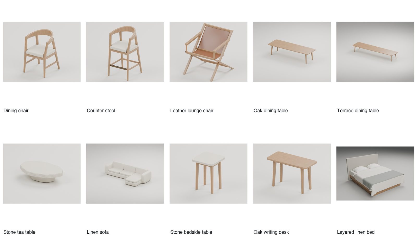
Ten components modelled in Blender. One shared component lets a correction carry through to every placement.
Inside one iteration: the dining chair
Image Gen established the form and material direction. Astra rebuilt it as an editable Blender assembly. Isolated renders exposed frame joints and cushion contact; corrections went back into the shared geometry and were checked again in the furnished room. These images show the reference and resulting model, not a complete chronological record of every revision.
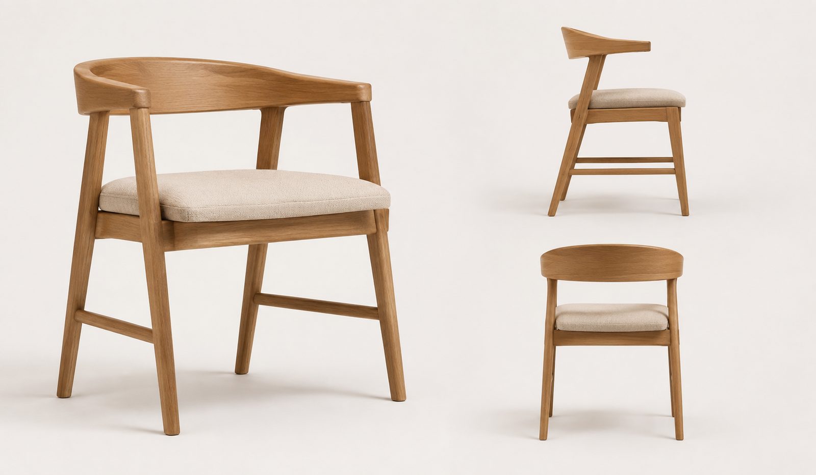
Image Gen: form and material reference.
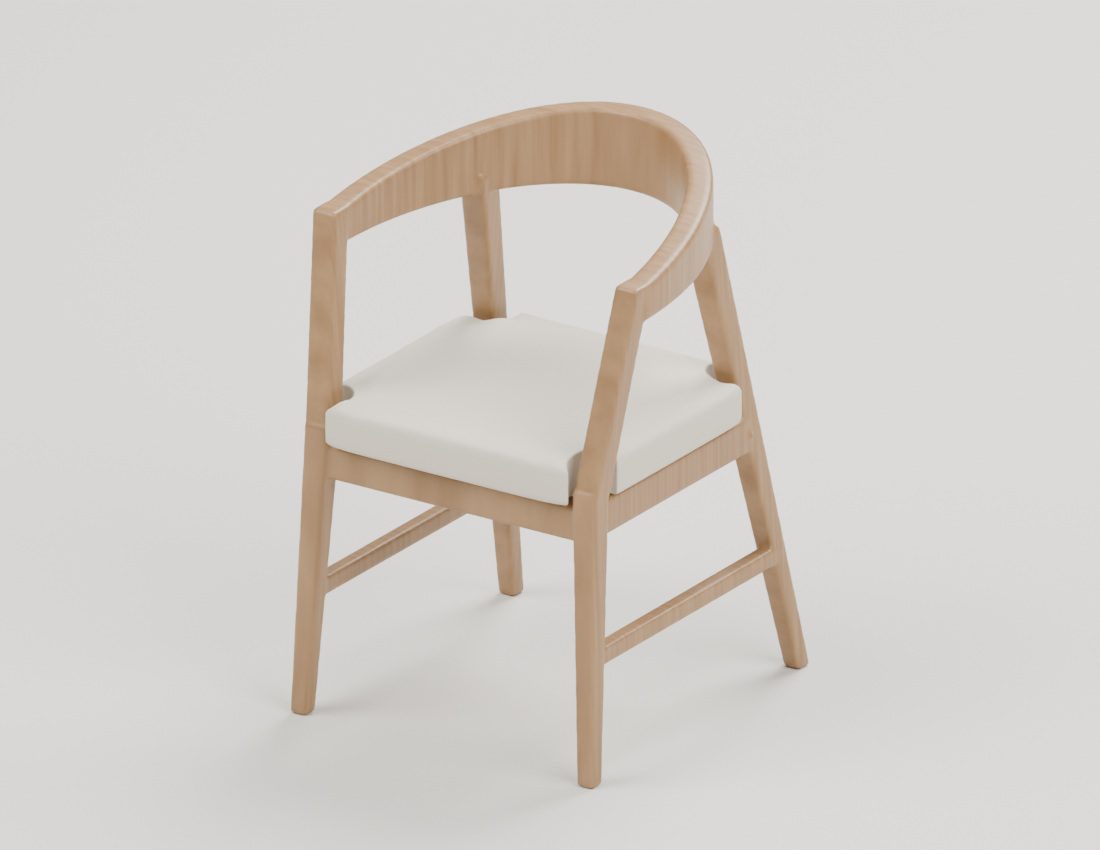
Blender: editable timber frame and fitted upholstery.
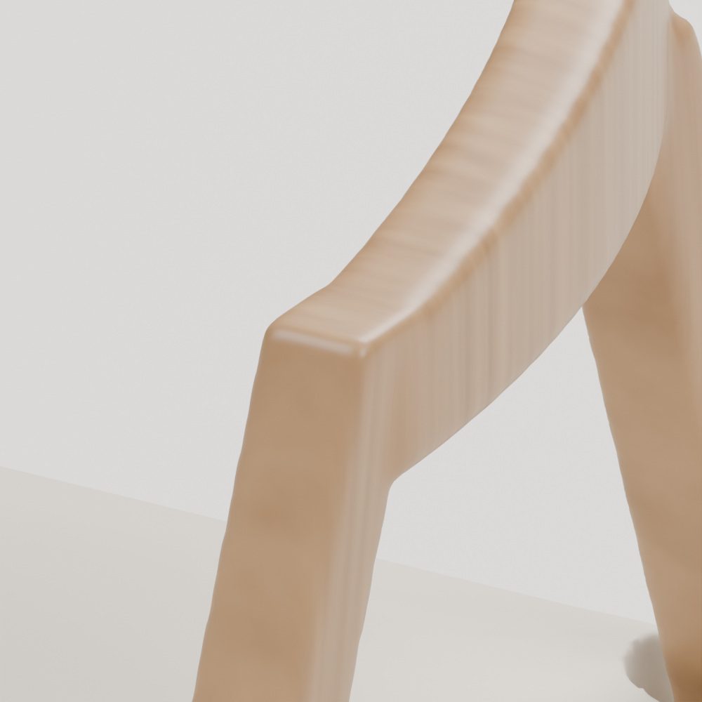
Isolated geometry review: check how members meet.
We compared Blender's two renderers on matching views. The bedroom test took about 64 seconds in Cycles and 52 in Eevee, and the lighting looked visibly different. Raising the sample count did not close the gap. We kept Cycles for finished images and Blender's quick preview for checking camera angles.
The house telescope, and how we would calibrate it
The telescope in the model is not a stand-in shape. We rebuilt it from published dimensions for a PlaneWave CDK17 on an L-500 mount with an equatorial wedge, so tube, mount and enclosure sit against real measurements. Its stated optics are a 432 mm aperture and 2,939 mm focal length. CDK17 specifications
The views below show the reconstructed instrument, its mount connection and its proposed ground-level enclosure. They are our drawing-based exterior reconstruction, not factory CAD or an optical performance simulation.
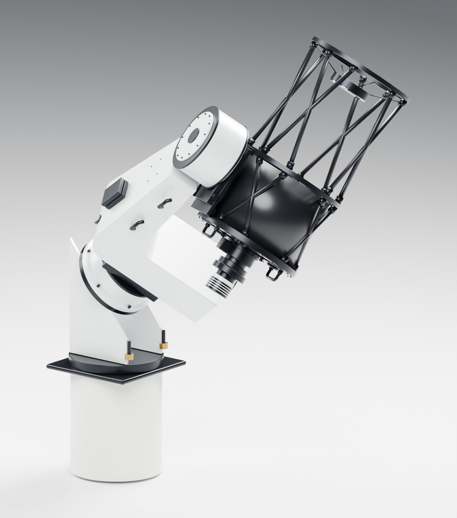
Telescope and mount. Rendered in Blender · Darkmatter / Casa do Poente.
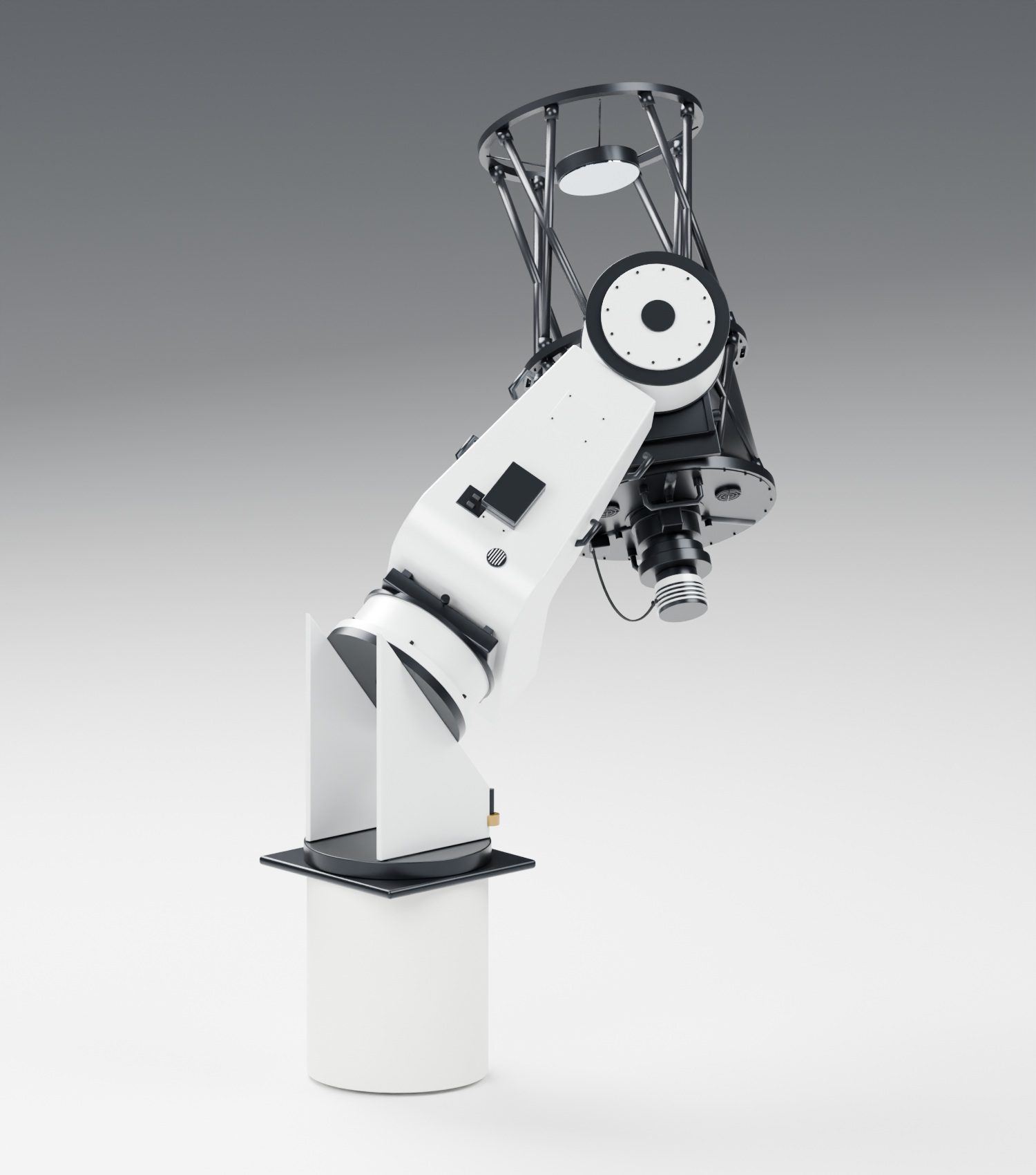
Rear view showing the optical tube, accessories and mount.
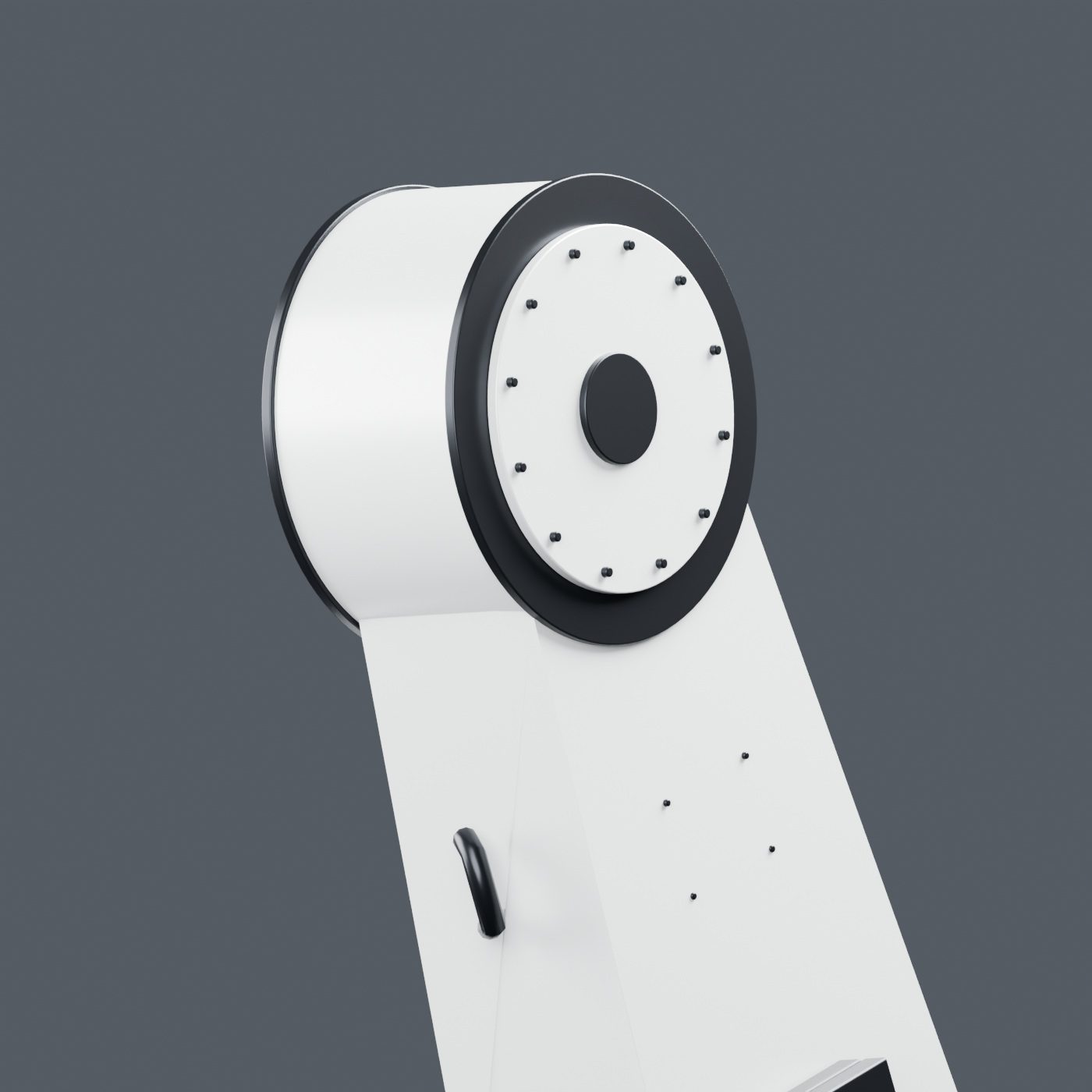
Detail of the mount arm joining the circular axis housing.
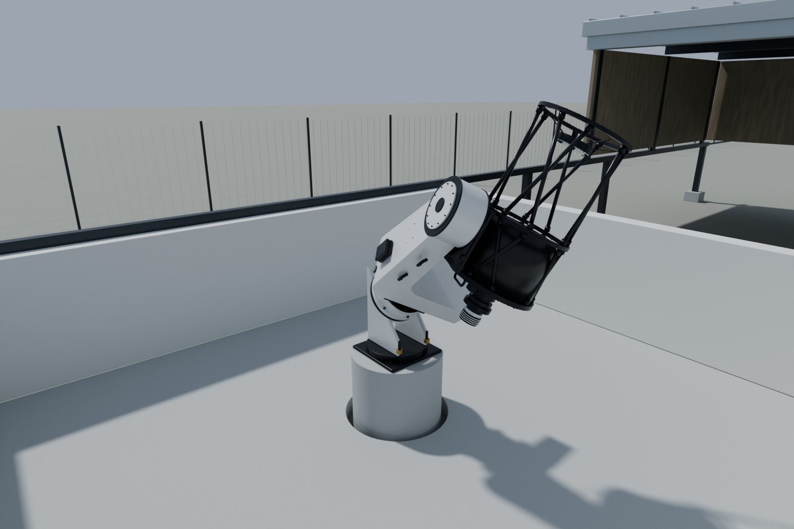
Ground-level flagship room: the current PlaneWave model in its dedicated ground-level room. The tower observatory has been cancelled.
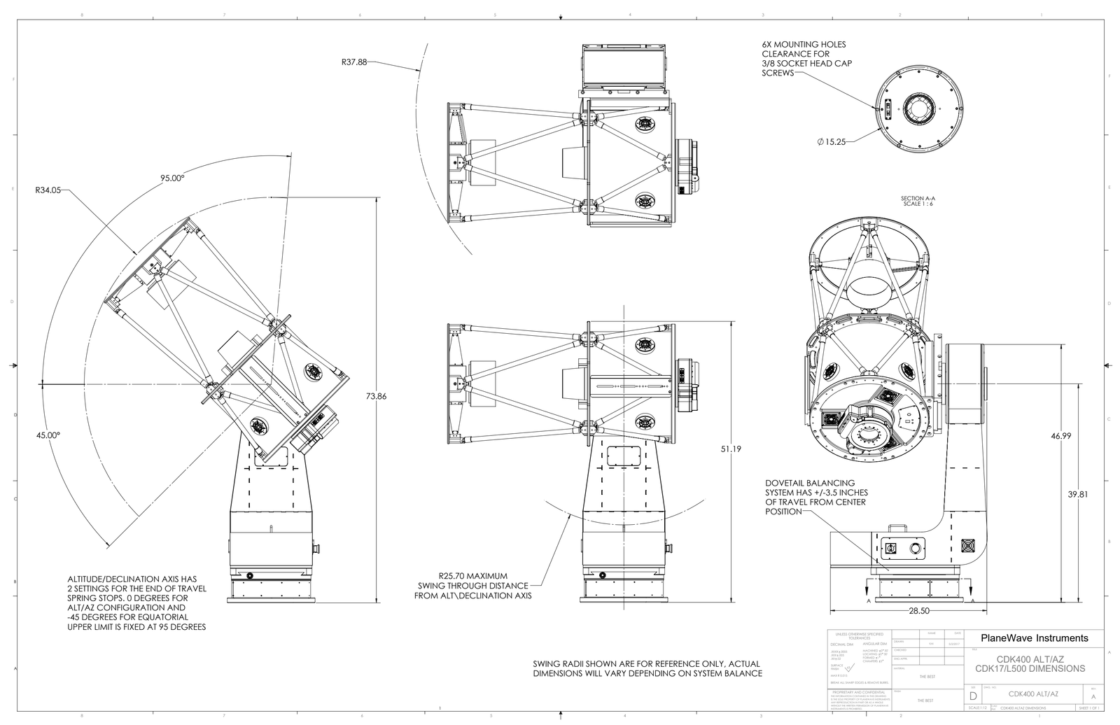
PlaneWave Instruments: CDK400 overall dimensions. This drawing gave us the measurements we rebuilt from. Original PDF.
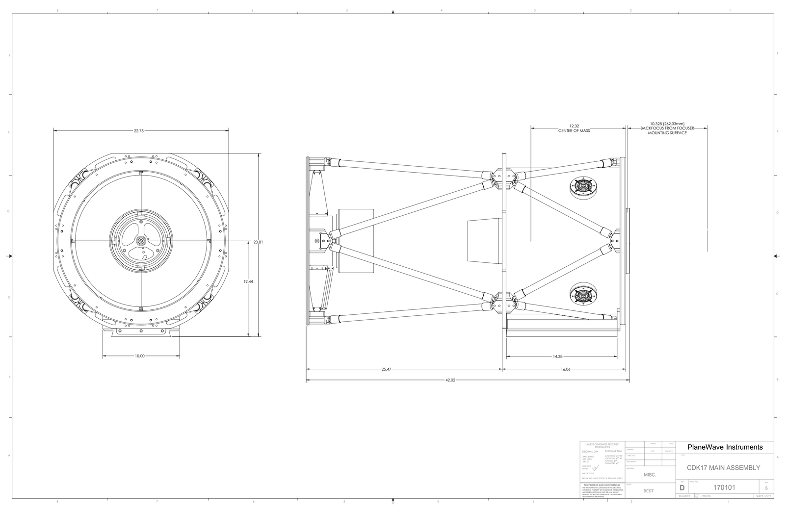
PlaneWave Instruments: CDK17 overall dimensions. Original PDF.
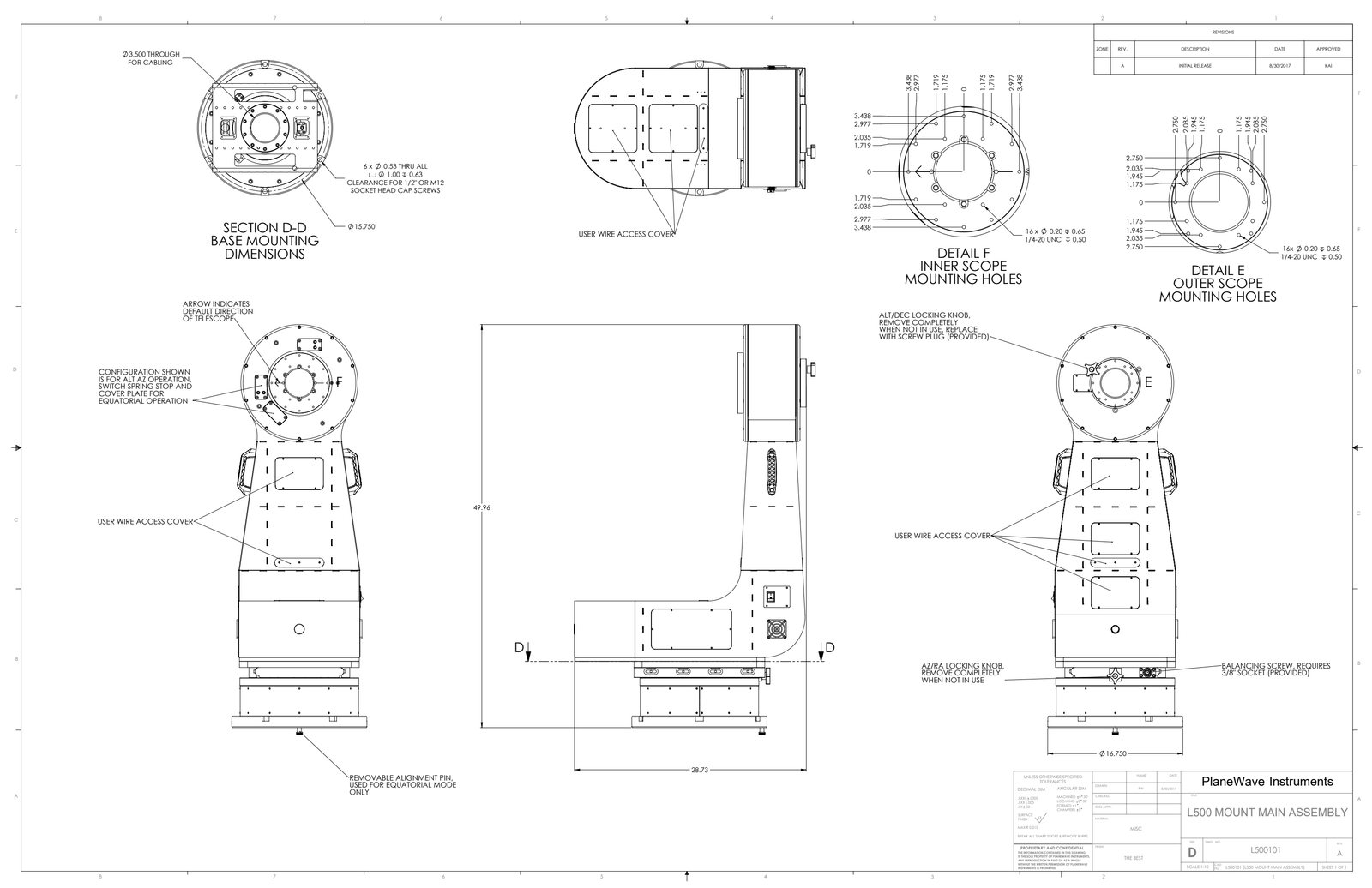
PlaneWave Instruments: L-500 mount main assembly. Original PDF.
In the earlier tower design we swung the telescope through 208 positions, and nothing hit the dome, the floor, the guards or the workstation in the poses we sampled. We cancelled that design later, for reasons unrelated to clearance.
We have not chosen a camera. As an example, a sensor with 3.76 micrometre pixels would sample the sky at 0.264 arcseconds per pixel. On a 36 by 24 mm sensor that is a field of about 42 by 28 arcminutes. At that scale small errors show, so we would have to calibrate polar alignment, pointing, focus, camera tilt, mirror alignment and tracking together.
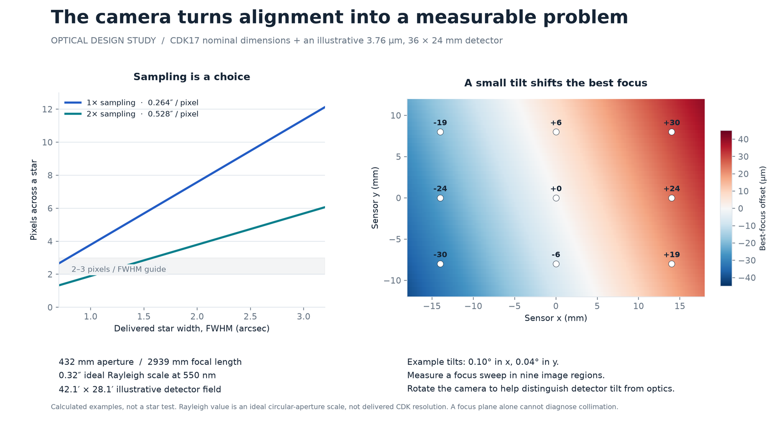
A study built around that example camera. The nine-region pattern is a proposed focus test, and the colour map a calculated tilt example.
On the real system we would let everything settle to temperature, follow the manufacturer's alignment procedure, then collect focus sweeps and star images across the sensor. Rotating the camera tells us whether an uneven focus pattern follows the camera or stays with the telescope. PlaneWave sets the spacing between the two mirrors at the factory, and it rarely needs adjusting. PlaneWave collimation and spacing instructions
The windmill review moved the observatory to the ground
The windmill was going to carry the telescope on a deck above a lounge. In plan it worked. Then we cut the tower open in Blender and saw what the drawing had hidden. A concrete pier stood in the middle of the room. A precision instrument sat directly above footsteps, warm air and an old structure we had never measured. We did not select that layout.
Instead, the telescope moves to a ground-level observatory, while the windmill becomes a lounge. The revised windmill has a tall open interior under an ordinary closed roof: no dome, no observing deck, no telescope support, no stair. Nobody has physically tested the old tower.
What the pier study changed
The option we rejected gave the telescope its own route to the ground, separate from the tower. It used a 900 mm concrete shaft, a steel box carrying the load sideways at the top, and a short stub above. As a way of carrying weight it works. As a piece of a room it is a permanent column: about 0.64 square metres of floor before anyone allows space to walk around it. The one-metre hatch above costs another 0.79 square metres of observing floor, beside the spiral stair.
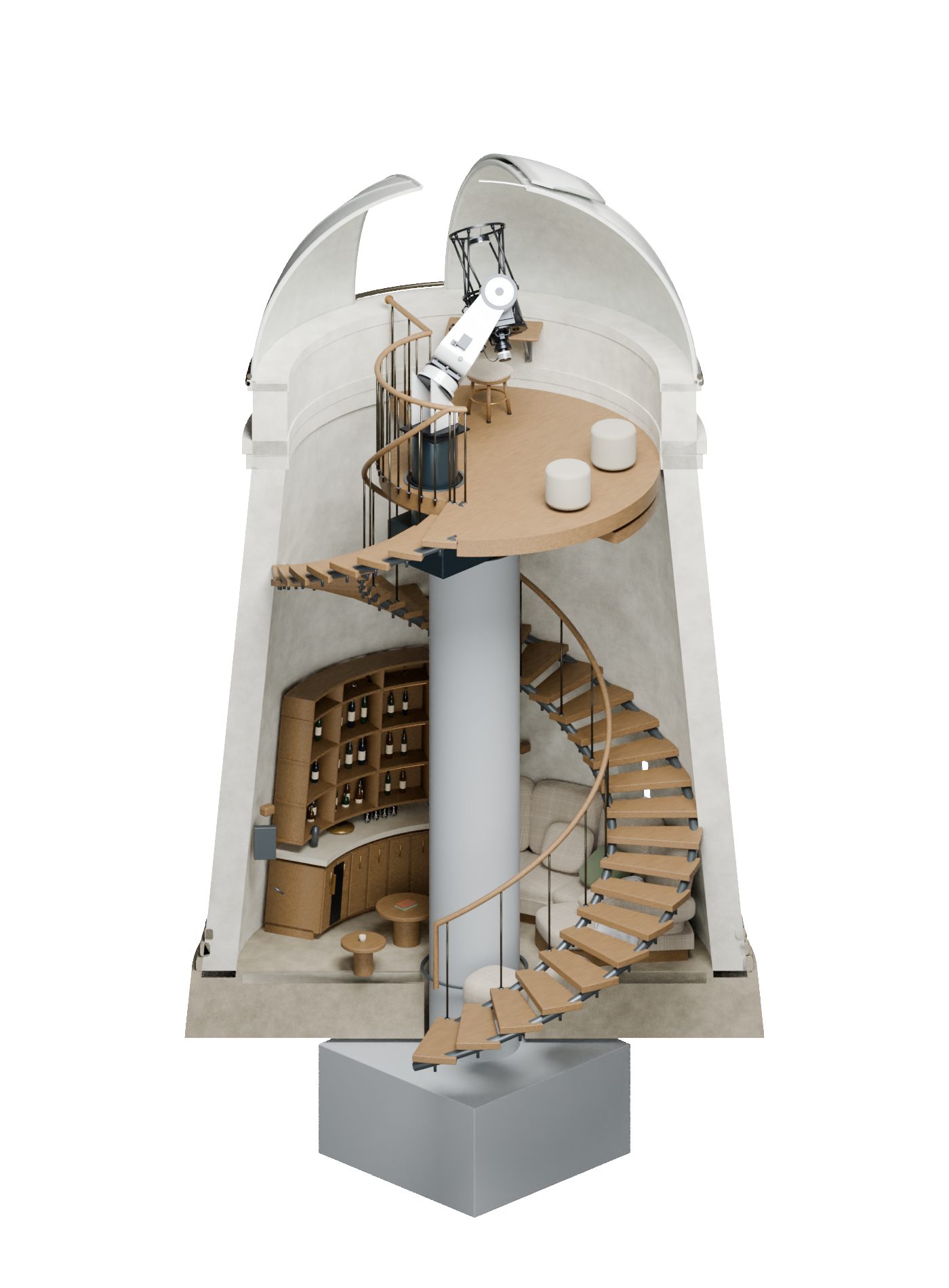
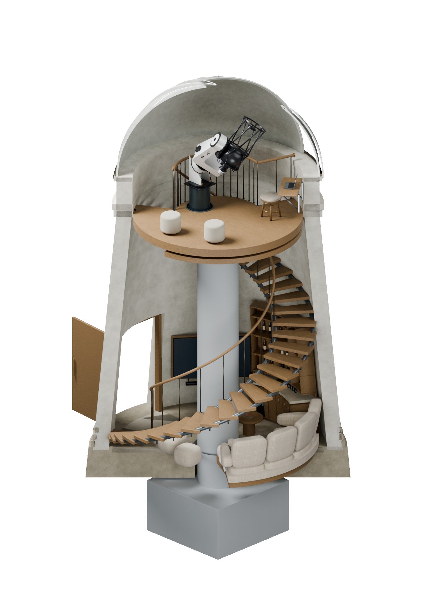
The rejected support from both sides, with the spiral stair, the observing floor and the hatch. Our checks here were geometric: the parts clear one another. Whether enough usable room is left is another matter.
Building it would have meant digging inside an old structure, cutting holes through its floors, installing heavy steel and raising a dome above it all. A frame around the walls could have kept the centre clear, but it pushes columns and foundations towards the tower wall and needs its own frame around the stair. That version stayed on paper.
The calculation also showed that the ground matters more than the pier. With the same 900 mm shaft and an assumed 270 kg load, the lowest vibration frequency fell from 11.6 Hz with a fixed base to 7.9 Hz with an assumed flexible foundation. Both numbers come out of a simplified two-dimensional model, with assumed soil stiffness and no twisting, joint behaviour or real loads, and the tower's own response is still unmeasured.
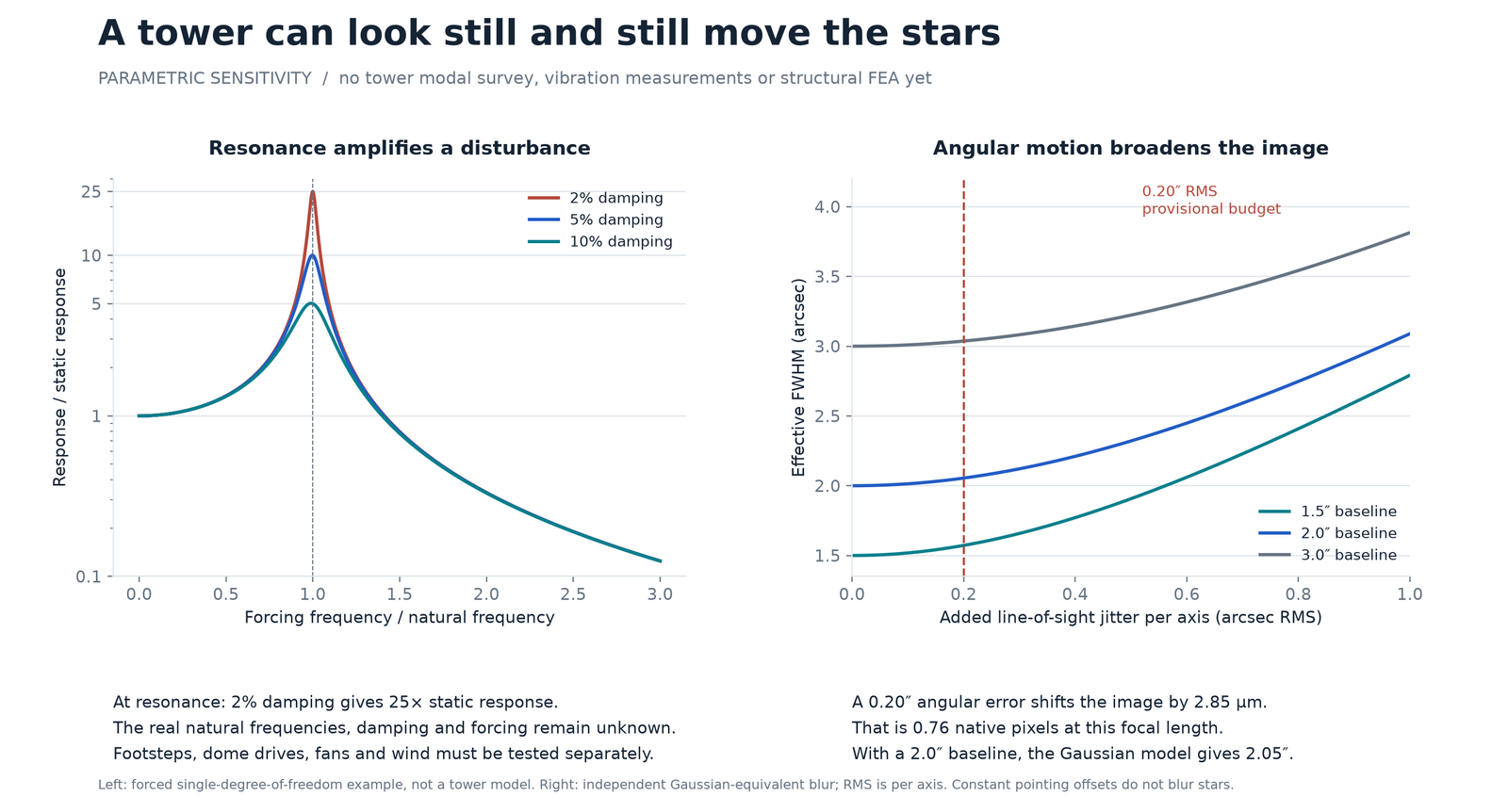
A general vibration response and an allowance for image width. Both bear on the imaging question rather than on any one support, and sizing the ground foundations is separate work.
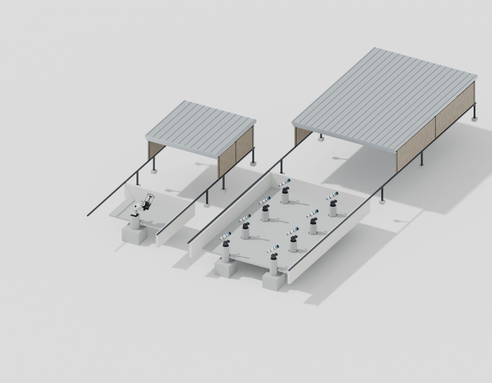
A section through the main telescope bay and one customer bay. Near wall panels and the front of the floor slabs are cut away to show the separate piers and footings. It was drawn for the earlier bay of eight piers, so read it for the principle rather than the count. Compare them with the shaft through the lounge above.
That view was drawn for the earlier bay of eight piers, so read it for the principle rather than for the count. Every instrument reaches its own footing, and nothing passes through a room below.
Moving outside costs us land, new foundations, weather enclosures and services. What it buys is a lounge nobody has to work around, and a site where we can add telescope bays instead of being stuck with one.
The drawing hid the conflict. The cutaway showed it. The calculation tested the alternative, and the building changed.
An observatory that can grow
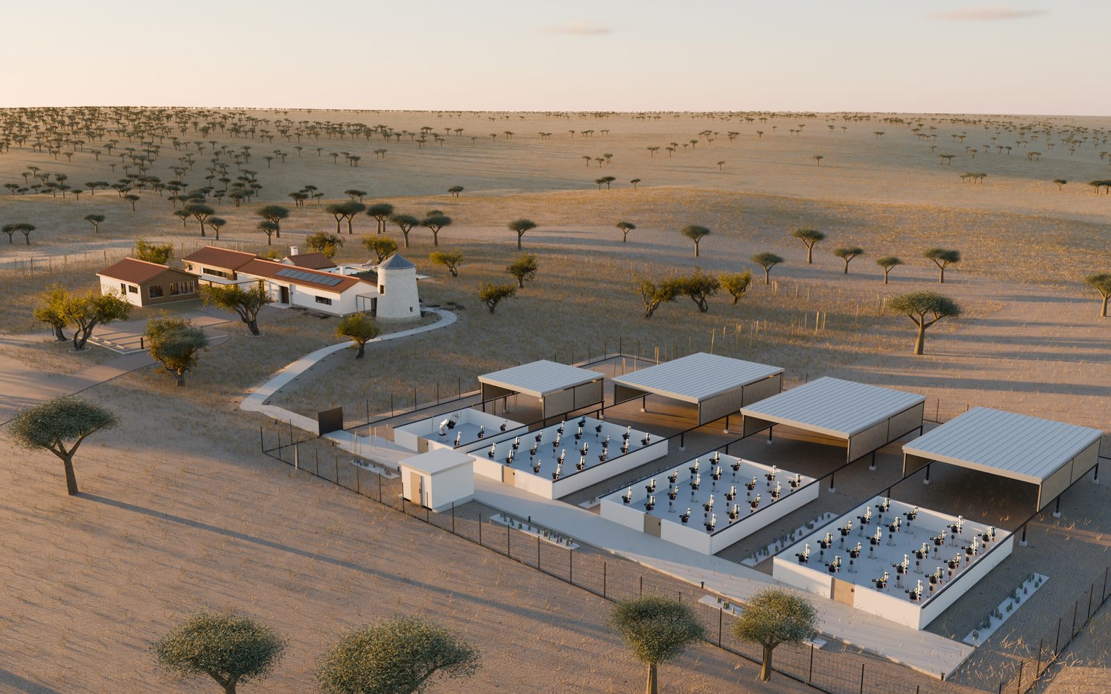
The whole site: the house and the windmill lounge on one side, the fenced campus with its four observing rooms and their parked roofs on the other.
The site has three shared hosting bays, every one 8 by 12 metres clear. Beside them sit a 6.6 by 7.2 metre room for the main telescope and a 3 by 3.6 metre pod for power, networking and dry servicing. Each shared bay now holds twenty compact stations, four columns by five rows, which is 60 shared instruments across the three. The PlaneWave keeps its own room and its own short concrete support, and gains three companion instruments along the enlarged eastern side.
That density comes from a smaller admitted envelope, not from a bigger building. Every shared station reserves a radius of 0.65 metres and a height of 2.6 metres. The height is unchanged; cutting the radius from 1.1 metres is the whole reason twenty positions fit where eight did. The layout has a 1.4 metre central aisle, 1.1 metre cross aisles, 0.5 metres between the closer paired envelopes and at least 0.2 metres to the walls. That allowance also decides who can be a customer: the count holds only for compact equipment that fits inside it, and says nothing about capacity for arbitrary customer rigs.
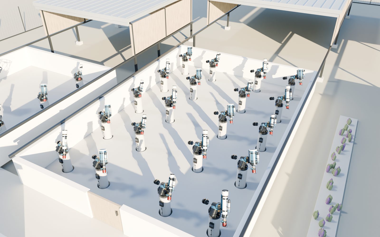
One shared bay with twenty compact stations, four columns by five rows.
Three generic compact assemblies of our own stand in for a 120 mm imaging refractor, a 200 mm reflector and an 80 mm wide-field refractor, at 141 to 154 parts each: optical tube, mount drives, filter wheel, cooled camera and cables. They are interpretive models, not vendor CAD and not a purchase specification, and one shared piece of geometry is instanced across the stations.
The audit of the built model records 64 foundations and 63 compact assemblies. Measured in the poses shown, the geometry fits inside a radius of 0.648 metres and reaches 2.075 metres high, both inside the reserved allowance. That is a check on shapes standing still, not on motion, loads or any vendor requirement.
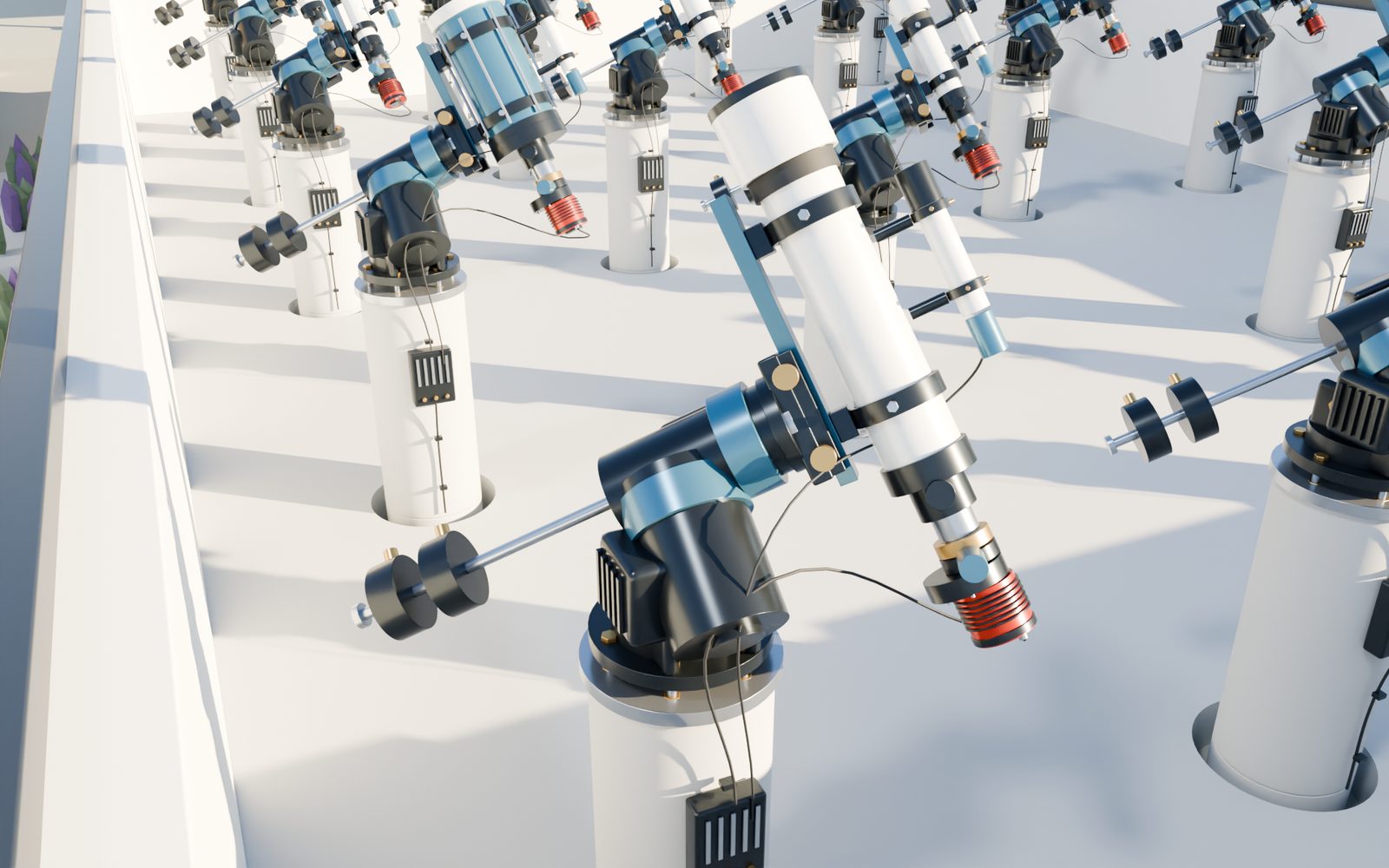
A station close-up. These are our own generic instrument models, not vendor CAD and not a purchase specification.
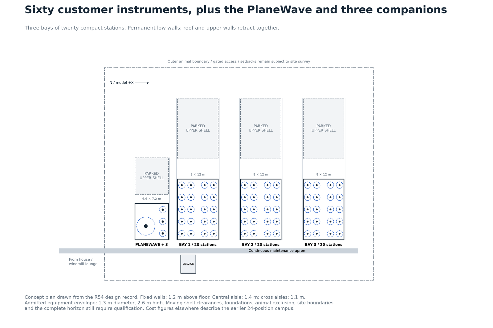
Drawn from the design record. Aisles, envelopes and wall heights are as modelled; the boundary, foundations and horizon still need site work.
The main telescope room grew from 5.4 by 5.4 metres to 6.6 by 7.2 metres to take the companions. Their reserved envelopes sit at least 1.019 metres clear of the 1.8 metre plan allowance around the PlaneWave. Each support rises through its own opening in the floor slabs, with 55 millimetres between the shared concrete piers and the walking slab. The blocks drawn underground reserve space for footings that a ground engineer has yet to size.
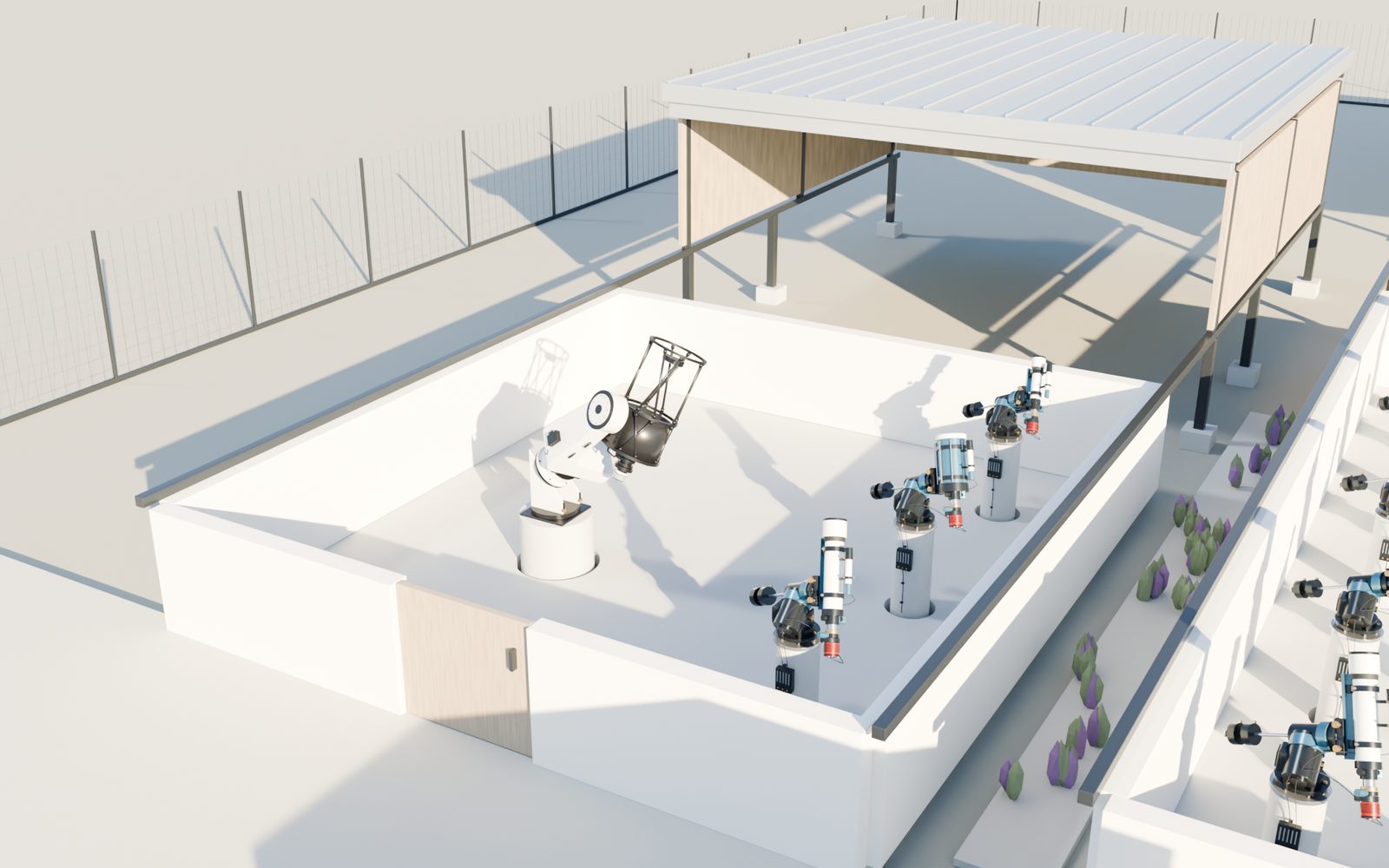
The enlarged main telescope room, with the PlaneWave on its mount and wedge and three companion instruments along the eastern side.
Starfront's Texas facility changed how we thought about the architecture. Its photographs show fixed piers inside permanent walls, with the roofs parked outside the bays rather than over them. We adapted that into permanent 1.2 metre walls, closing gates and low rails. Roof and upper side walls retract together, so no fixed high frame sits over the instruments. A separate 2 metre outer fence and gated entrance add a second layer against animals. Starfront gallery, facility details.
None of that enclosure changed when the instrument count did. The roof underside still sits 3.15 metres above the finished floor, and the upper enclosures still travel 9 metres for the main telescope and 16 metres for each shared bay. The carriages park behind the four observing rooms, and the front curtains have to be raised before the roof moves. How much horizon each telescope sees depends on those parked roofs, the neighbouring bays and the fence.
We ran the same 208 positions against the telescope room and its roof planes, which clears part of the geometry. That sweep was run on the earlier, smaller room, and the PlaneWave assembly has not moved since, so the larger room with its three companions still rests on that limited pose study rather than a new mechanical qualification. The rest of the list is long, and we know it: full mount movement, cabling, the moving walls and roof, wind and heat moving the short piers, animal mesh and cable penetrations, and how the site behaves if a control system fails.
At the scale of that example camera, 0.20 arcseconds of image movement is 2.85 micrometres at the sensor. That is the target we would test against, and neither support design has met it yet.
What telescope hosting would have to earn
Moving to the ground also made hosting worth studying as a business. Customers bring their own instruments, and we would supply protected space, power, connectivity and technical support. The PlaneWave stays a separate first instrument for commissioning, science and guest use, and none of its earnings prop up the hosting figures.
Every number in this section was worked out for the earlier build of 24 customer positions in three bays of eight. None of it has been recalculated for 60, and the model cannot be stretched: it prices a bay as eight piers, steps its staffing at 48 piers, and refuses to run above 48 at all. The figures below describe the campus we costed, not the campus we have now modelled. Geometry is cheap to revise and a business case is not. Re-running it is the open question this expansion creates.
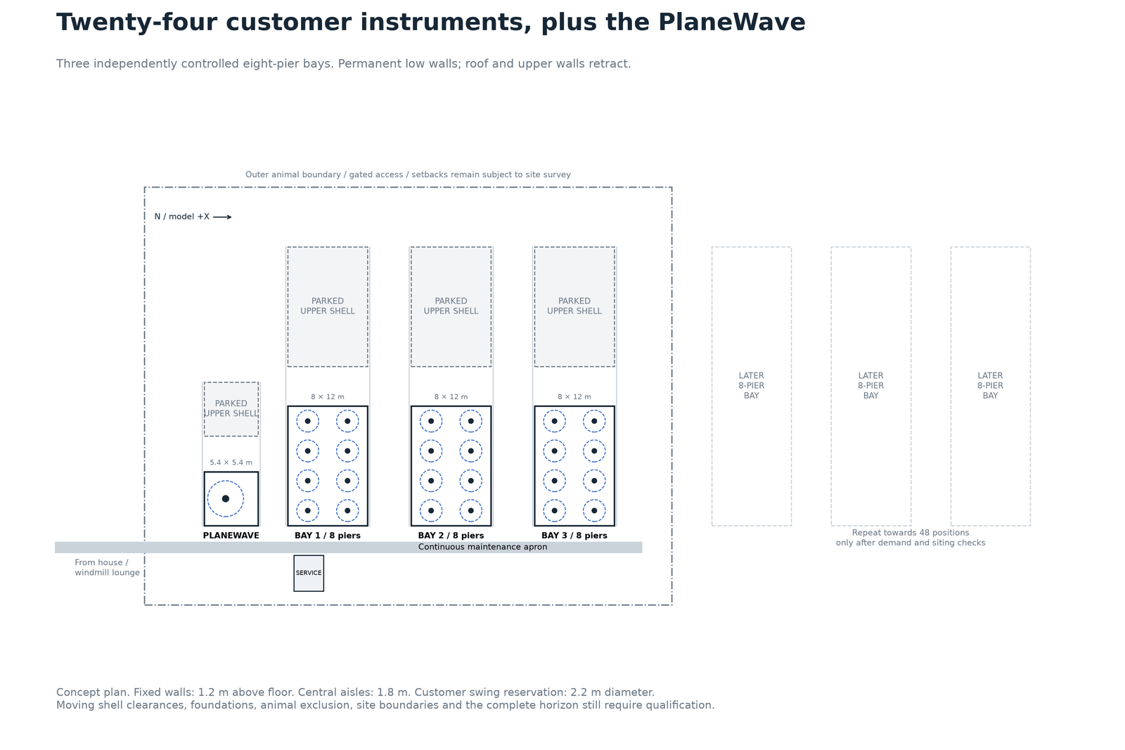
Three bays of eight piers plus the main telescope. Dashed blocks reserve room to grow towards 48 customer positions, set relative to one another rather than to a boundary line. That plan draws the campus the money describes, not the one we have now modelled.
Three operators give us a market to read. Starfront in Texas charges US$149–399 per month for a dedicated pier, depending on the swing allowed. Astro ARO in Portugal, a nonprofit association, starts at €280 including VAT, or €227.64 net. PixelSkies in Spain charges €300 plus VAT for two telescopes and two cameras per pier. They sell different products, so copying the Texas model in Portugal hands us no price advantage. Starfront, Astro ARO, PixelSkies.
Capacity turned out to be a pricing question. The bay we costed reserved 1.1 metres of radius around every pier. Measuring the same 8 by 12 metre footprint differently suggested eight large, twelve standard or sixteen compact positions, none of them rebuilt or collision-checked at the time. Compact is the direction the model took, and it went past the sketch: twenty stations per bay rather than sixteen, on the 0.65 metre radius described above. The pricing consequence has not changed: more piers mean more circuits and more support work, and smaller instruments expect a lower price. Thirty-six standard positions at an illustrative €300 and 48 compact at €225 bring in the same revenue at equal occupancy.
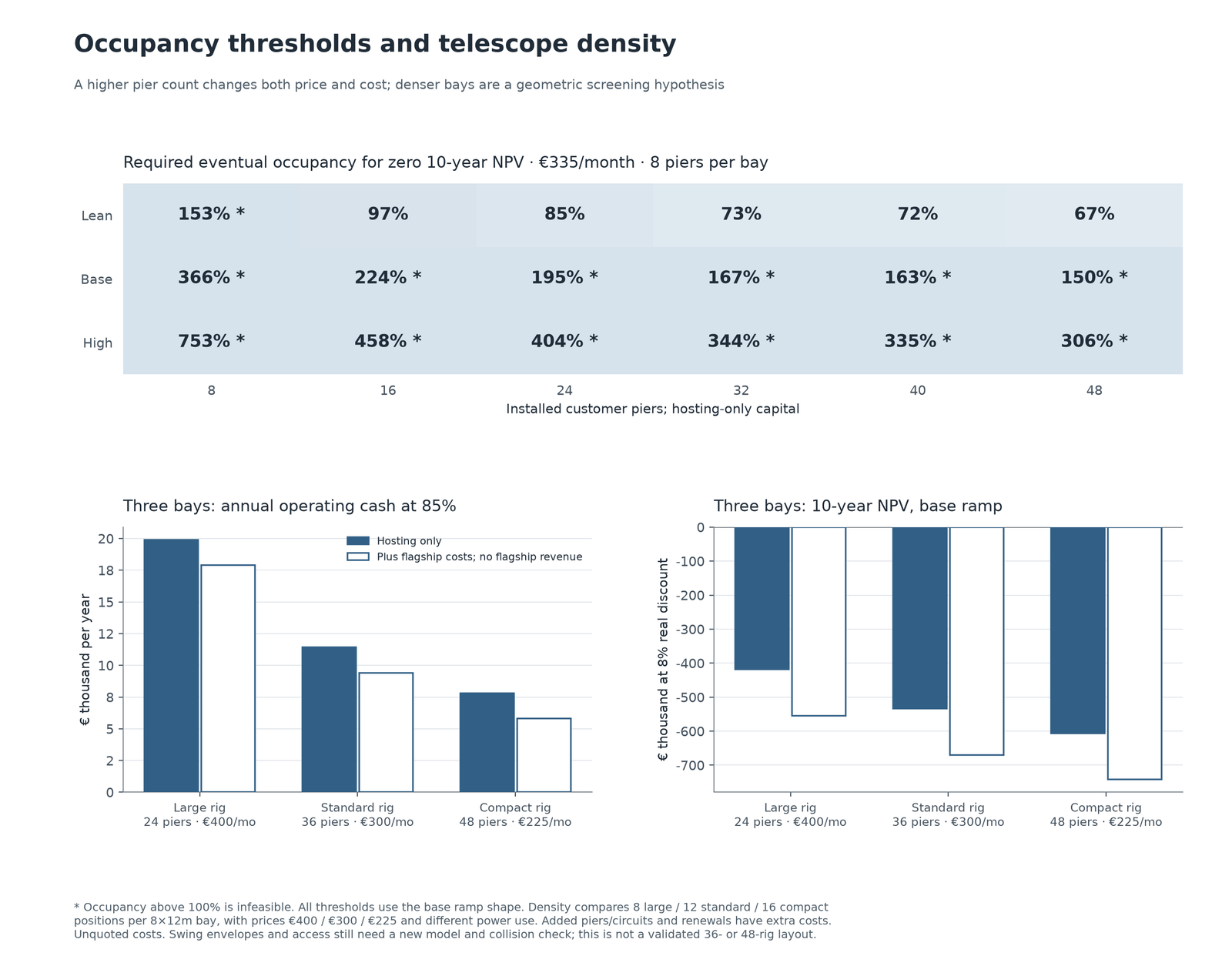
Break-even occupancy against assumed prices, and the effect of telescope size and bay density. The density options are planning sketches over the same footprint, and the full study separates customer positions from telescopes and paying customers.
We then built the model out with shared construction costs, staffing steps, maintenance, renewal and a ten-year cash flow, against slow, base and fast take-up. At a hypothetical €335 average net monthly price, the lean cost case leaves 24 positions worth about €2,400 in today's money, after the assumed 8% return. That is a rounding error, not a business. The same case at 48 positions gives about €180,500, and the higher cost case misses the target at every capacity we tested. Every input is an assumption and nothing is quoted, so the result shows what to test, not that a bigger site pays.
The useful test is therefore a ceiling on cost: given a price customers accept, how much can we afford to build? Under the lean assumptions the break-even average price falls from about €333 at 24 positions to €269 at 48. Supplier quotes and customer commitments would tell us whether either is reachable. The lower-price market already exists. Our question is whether we can serve it reliably at a margin worth having.
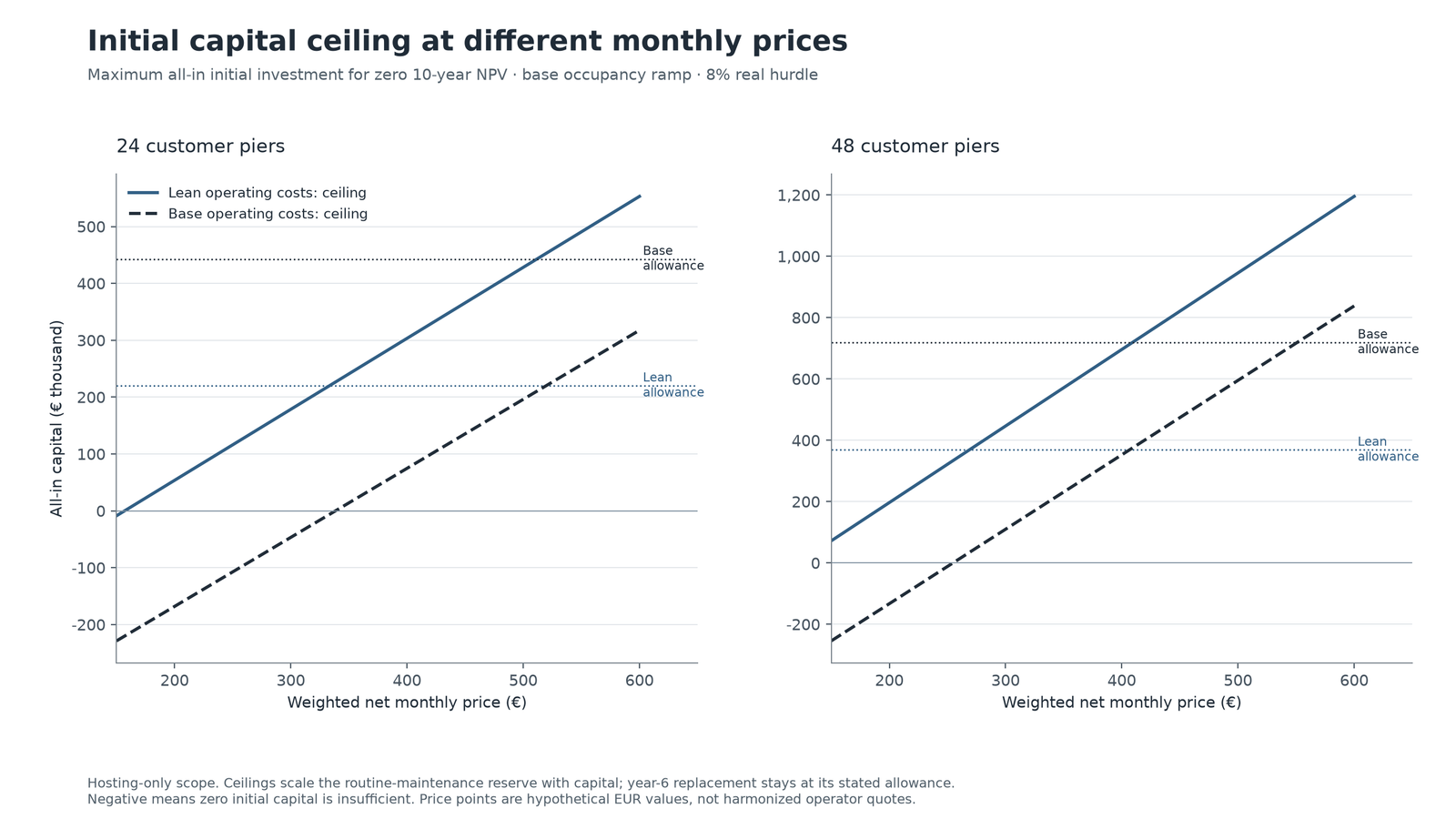
Hosting only, including the shared observatory works. The curves solve for a ten-year result of zero under the stated take-up, with the PlaneWave assessed separately. A negative ceiling means that even with no money spent up front, that cost case does not work.
The next comparison is between standard-equipment and large-equipment bays, with compact hosting as a separate offer. We would reserve room to expand, then build against costed designs and visible demand. A pilot of eight positions would teach us how to run the site, without paying back the startup infrastructure on its own.
Planning and controlling an observing night
Before sunset, a scheduler works out which patches of sky will be observable and when. Through the night, observing software holds the focus, matches star patterns to confirm where the telescope points, watches the tracking and grades each exposure. The images and logs become the record of the session.
We calculated an example for the night of 10–11 September 2026 near Évora. Full astronomical darkness runs from about 21:18 to 05:38 local time on our two-minute grid. The queue holds time back for setup and closure and revisits targets, rather than assuming the whole night becomes exposure. Skyfield almanac methods
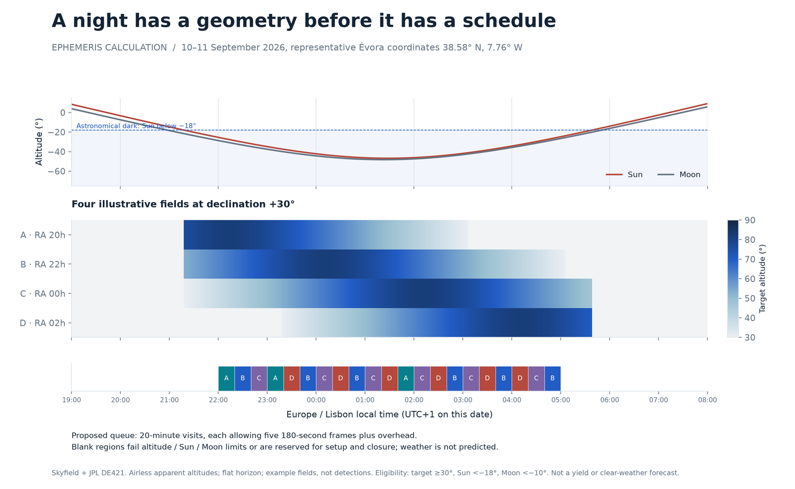
Calculated with Skyfield and JPL DE421. The queue is a worked example: its 315 minutes of allocated exposure show how a night could be divided, not how much of it the weather would hand back.
The design keeps AI-assisted planning and interpretation on one side of a line, and a simple, predictable safety layer on the other. Rain, unsafe wind, a stale sensor reading, a communications fault or a mains power cut each need a tested response. The hardest case is the dull one. A customer's computer or mount stops answering while the telescope is still pointing somewhere awkward. The enclosure needs a proven way to reach a safe state from there, with a closing sequence that cannot collide with the telescope.
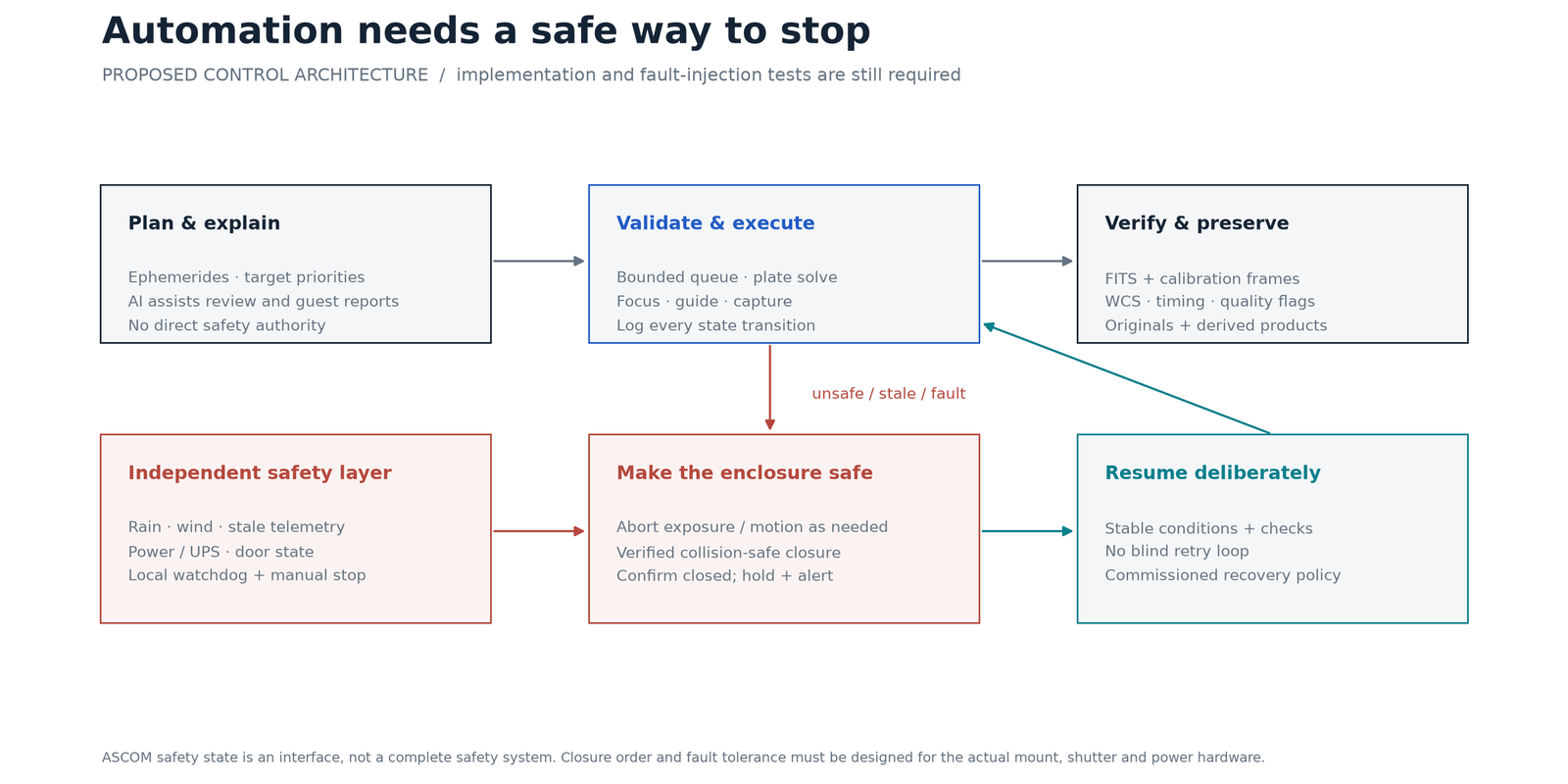
The architecture is proposed, not built. ASCOM, the standard way astronomy software talks to equipment, reports the safety state. The watchdog, interlocks, closing sequence, backup power and recovery policy still have to be built and tested. ASCOM safety-monitor interface
The morning report could carry calibrated images, the conditions each exposure was taken in, and the reasons frames were rejected. AI would write the account of the night from the images and their recorded data. On a cloudy night it would record why observing stopped.
Hospitality shaped by the sky
Portugal already has established astrotourism operators, and Dark Sky Alqueva is a Starlight Tourism Destination with observing experiences and hospitality partners. Casa do Poente explores something much smaller: a single property with its own observatory. "Dark-sky-first" describes our design priority. It is not a certification, and we make no claim to be first in Portugal. Dark Sky Alqueva
The windmill lounge gives guests somewhere to sit out a cloudy night. The library and workshop could host artistic work made from the observatory's own images and observations.
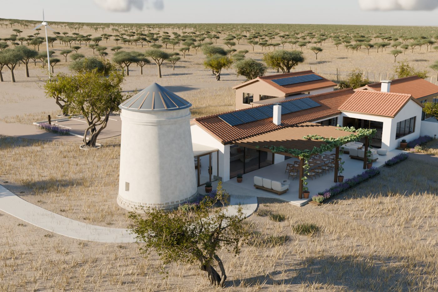
The windmill keeps its place on the estate as a lounge and interpretation space, under the plain roof that replaced the dome.
Use the study to try the approach on an idea of your own. If you would like to develop it with us, talk to Darkmatter.
Darkmatter is a hardware, software and AI lab based at Poolside Santos in Lisbon. Casa do Poente is a freely shared case study of its AI-assisted design and modelling workflow.
A few views from the model
These six views come from an earlier round of the design. Where a windmill dome is still visible, it belongs to the tower we cancelled.
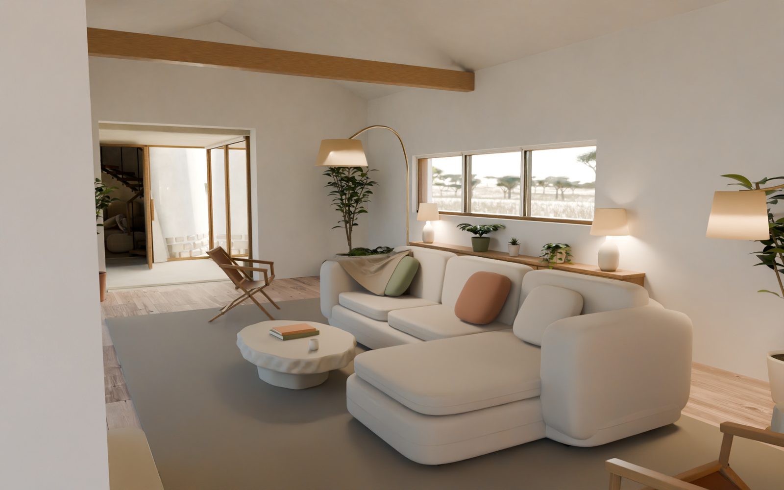
Living: soft seating, the carved stone table and the connection towards the windmill.
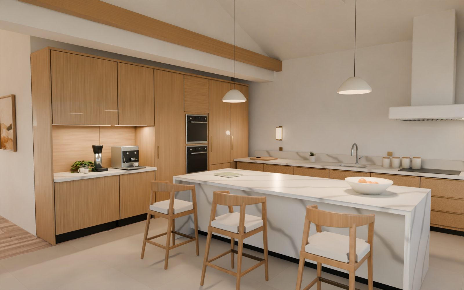
Kitchen: fitted joinery and the reusable furniture family in context.
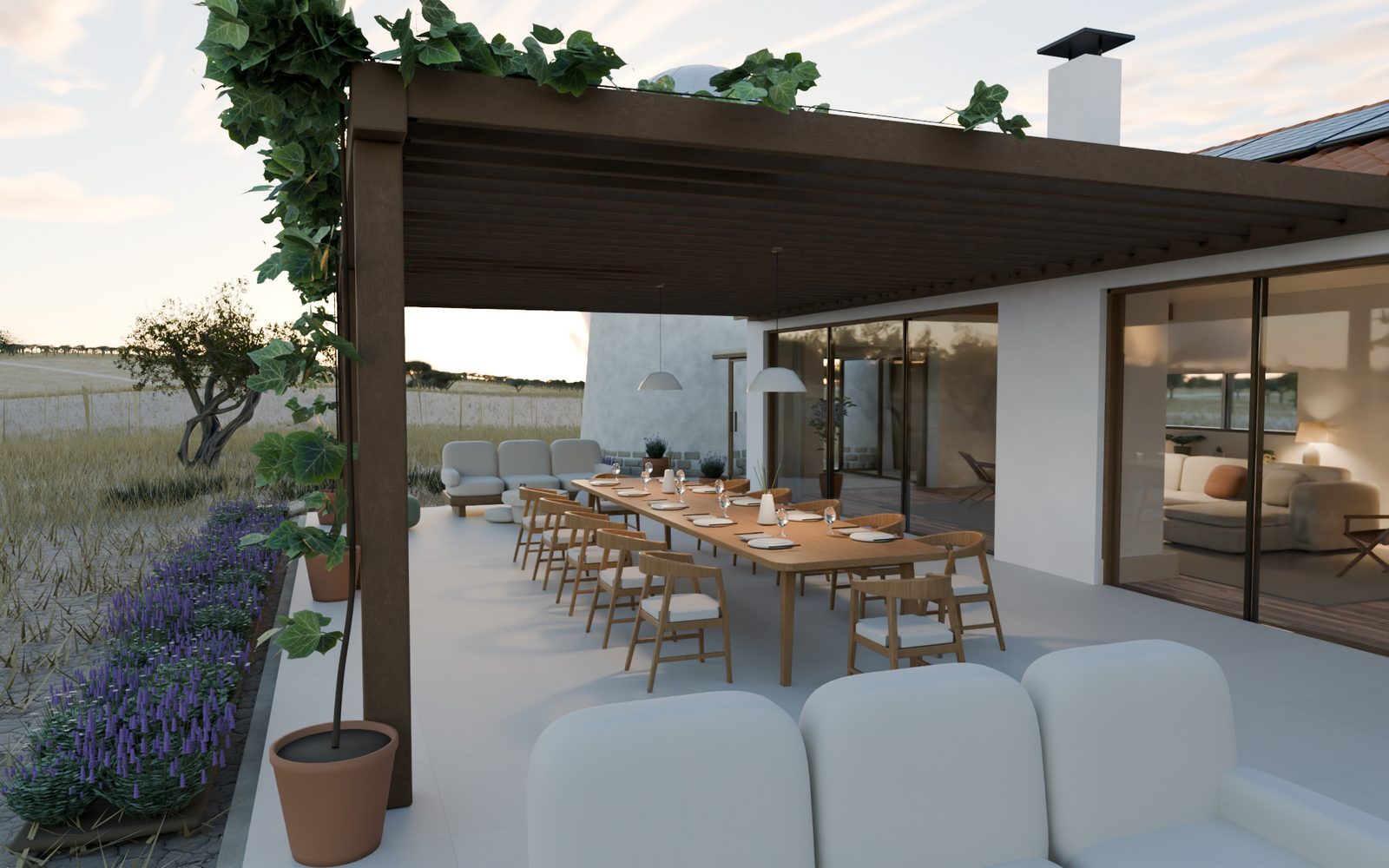
Terrace: outdoor dining under the planted pergola, connected to the living spaces.
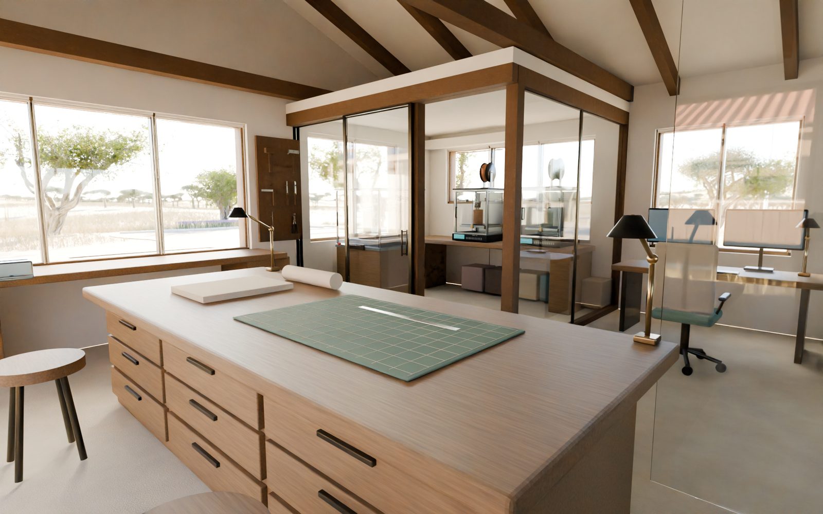
Studio: a place to build and learn during the day, or when clouds interrupt observing.
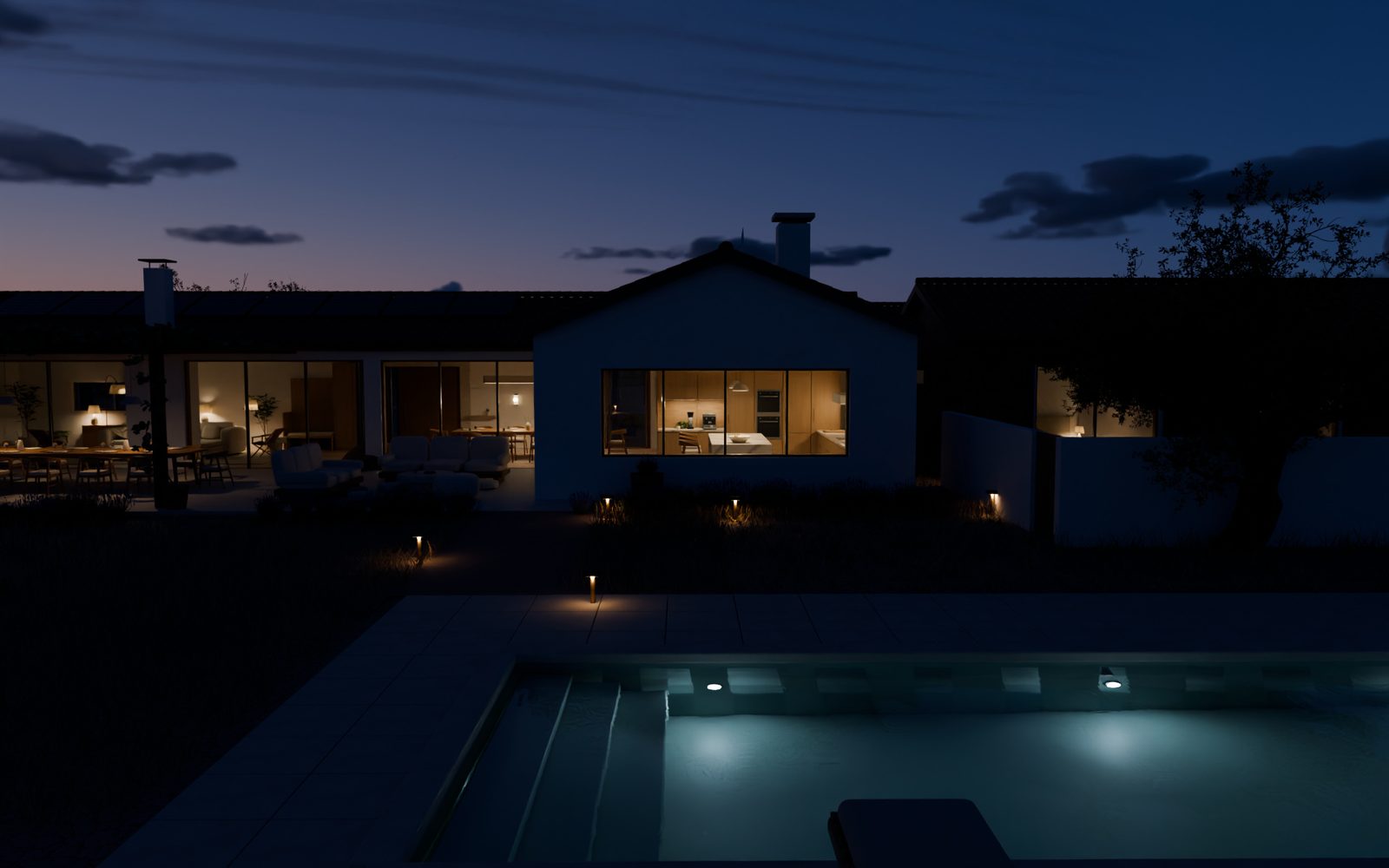
Pool: the evening leisure lighting. Sensitive observing would use a different state.
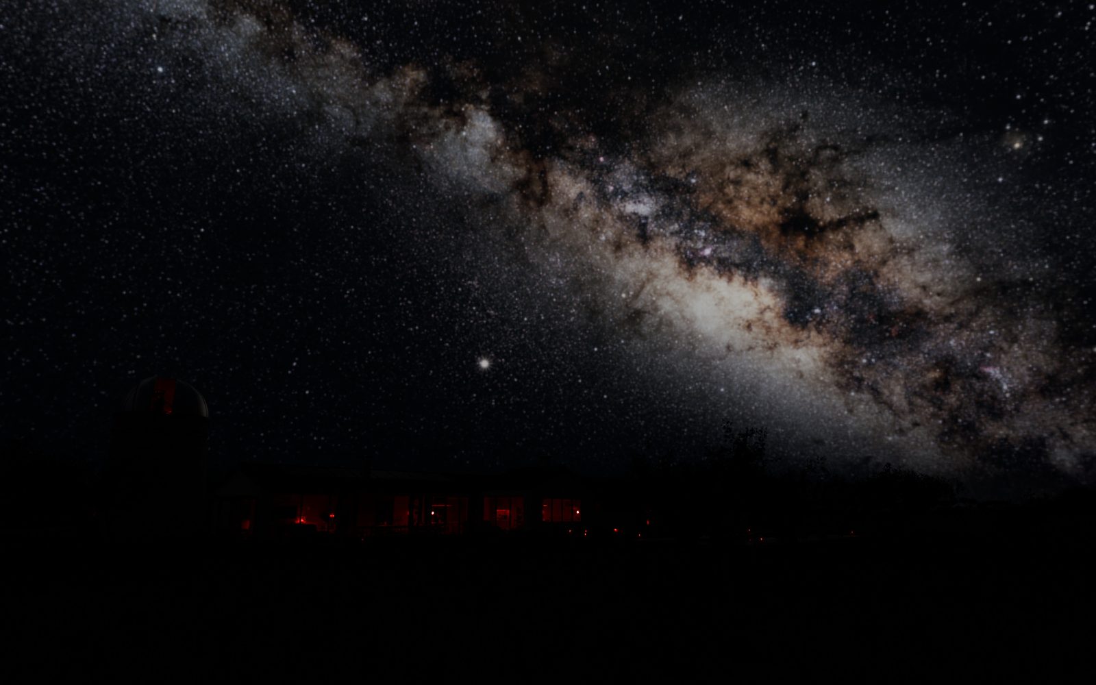
The Milky Way behind the tower is an illustration, ESO/S. Brunier, CC BY 4.0, placed into the render rather than photographed on site.